June 1, 2019 - by Paul Bosselaar
So we’ve seen how we can call the BIOS and how to use an assembler to create a file which can be BLOAD’ed and run on an (emulated) MSX. So now that is out of the way, lets do the mother of all tutorials: Hello world!
This can be pretty hard to start with if you want to do this in screen 2 of the MSX. But let’s do this in screen 0 because then we can get some help from the BIOS. The BIOS has a nice call that can display a character on the screen called CHPUT. There are a lot of resources which list all the BIOS calls, e.g. http://map.grauw.nl/resources/msxbios.php , so of you want to get an overview of all the BIOS calls, start reading those ;)
The normal BIOS does not have a routine to display more than one character at a time, so to display more we somehow have to call the CPUT routine more then once. The Z80 running in our MSX has instructions for looping, or jumping to other parts of a program which we can use for that. What we’re also adding is some labels instead of numbers called in the code to call the BIOS routing. This makes our program a bit more readable when the program gets bigger. So, let’s dive in:
CHPUT:    EQU $A2

        DB $FE      ; magic number
        DW Begin    ; begin address of the program
        DW End - 1  ; end address of the program
        DW Execute  ; program execution address (for ,R option)

        ORG $C000   ; The program start at C000h in the MSX's RAM
Begin:
Execute:
        LD HL, HELLO

LOOP:   LD A, (HL)
        CP 0
        RET Z
        CALL CHPUT
        INC HL
        JP LOOP
HELLO:  db "Hello world",0
End:
The first line with the EQU instruction simply defines a label “CHPUT” with the value of $A2 (A2 hexadecimal). This is not an actual instruction for the Z80. EQU signals the assembler to simply replace the label (CHPUT in this case) with the number when in encounters the label somewhere else in the code. This way we can do CALL CHPUT instead of CALL $A2. This way we don’t need to remember that $A2 is actually CHPUT.
Right after that comes the BLOAD header and the ORG instruction we saw in part 1 and part 2.
So the first new instruction is LD HL, HELLO. LD stands for load and it can load values from and to the MSX’s memory and from or to so called registers.
Registers
A register can be seen as memory directly available to the CPU. There are different registers available, but for new we’ll only use two of them: The register A (aka accumulator or accu), which can hold 8 bit variables (e.g. 0-255) and the register HL which is actually a pair of 2 registers combined (H and L). As a pair it can hold a 16 bit value (e.g. 0-65535).
So to let the Z80 do something with something somewhere in memory, we usually have to load from memory to a register so the Z80 can do something with that register. In this case we load the label HELLO into register(pair) HL. So this means that HL now contains the memory address of HELLO. If we look at the end of the code we see that right after the label “HELLO” we define the bytes with the sentence “Hello world”. So HL now points to the letter H in memory.
Addressing
The next thing we need to to is load this letter H into A and call the CHPUT routine. The CHPUT routing will display the letter loaded into the A register. The instruction LD A, (HL) will load whatever HL points to in memory into A. If we where to write LD A, HL we would try to load a 16 bit value (a memory address in this case) in A. Since A can only hold 8 bits, that would be impossible. So the instruction LD A, HL will simply result in an error when assembling the program. This concept is an important one and is called “indirect addressing”. So without the parenthesis we do “direct addressing”, e.g load the value from one register into another. And with the parenthesis it’s “indirect adressing” and we load the value from memory where a register points to into another register.
Ok, so we loaded the letter H into register A. Now call the CHPUT routine right? Well, not so fast. We need to make sure we do this exactly 11 times. We can either try to make this loop 11 times or we can do something better. In this case we defined the number 0 right after hello world. So what we need to do is check if we loaded the number 0 into register A, and if that is the case, simply stop the program. This way we can change “Hello world” into anything we like and the program will still work without the need for us to calculate the lenght of the text we’d like to display. So to compare a value in register A, we can use the instruction CP (ComPare). CP will always compare the given value to the value loaded in A. The result of this comparison is stored in the Z80 flags.
Flags
Flags? First registers and now flags? Yes indeed, flags. The Z80 has so called flags to flag results of the last instruction the Z80 handled. Some instructions (e.g. LD) do not result in changing any flags. But others, like CP, do. The Z80 has different flags for different meanings. In our program we’ll be only using the Z flag. Z stands for zero. If the instruction handled resulted in 0, the Z flag is set. So how to use this with CP? What the CP instruction actually does is a substraction from the value in register A without storing the result (if you want the result, use the SUB instruction). But the flags ar still handled as if the actual result is stored in A. If that result is zero, the Z flag is set. So that means that if A and the value in CP are equal, the result well be 0 and the Z flag will be set. If they are not the same, the Z flag will be reset.
With the CP instruction we can also check if the value given is bigger or smaller than A. For that the carry (C) flag is used. If the value given to CP is bigger then A, the result would not fit, so the carry flag is set to signal that the result did not fit. If the result does fit, the C flag is reset. Not fitting in this case means a value below 0 or a value above 255 because the A register can onlyh hold 0 to 255. So if A is 1 and the value given to CP is 2, the Z80 will try to substract 2 from 1. This would result in -1, to the carry flag is set to indicate that.
There are different ways to let the Z80 act on flags. In this case we simply RETurn to Basic when the Z flag is set. The RET instruction by itself will always RET’urn the the place the code was called from, but there are also instructions to only RETurn if a flag is set or not set. In this case we use the RET Z instruction which will only RETurn when the Z flag is set. There are of course different varations of this instruction like RET NZ (return when the Z flag is not set) or RET C and RET NC (return when the carry flag is set/not set).
Print it
So, after all this text, we have only handled three instructions: LD, CP 0 and RET Z, which together check if we have 0 loaded into A and if so, RETurn to basic. Since the first value we load is H, which is obviously not 0, the program will continu. (Yes, H has an actual value attached to it according to the ASCII table, H as the value of 72).
So now we call the CHPUT routine which prints the charater to the screen. The next instruction INC HL will INCrease HL by one. Since HL contains a memory location, HL will now point to the next memory location, which contains the letter ’e’. So all we have left to do is jump back in the program to load the value into A, compare, stop if needed and print. We defined the label LOOP to point to that piece of program so we simply JP (JumP) to it with JP LOOP after we changed HL.
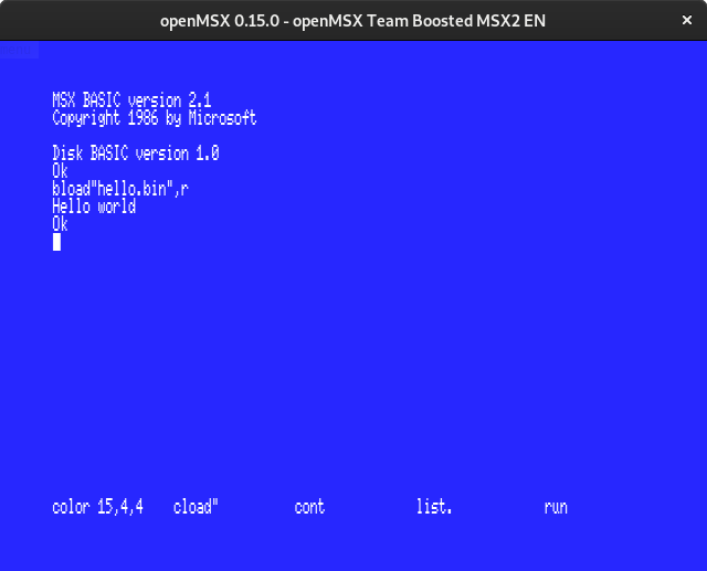
Assemble this program, BLOAD and run it and it should result in something like this:
Addressing again?
So we used INC HL to let HL point to the next byte in memory. Now we can also use INC (HL). What would happen if we do that? I’ll give the answer in part 4, so stay tuned.